|
 |
 |
 |
 |
 |
| Making a Curved Knife
|
 This
tutorial will show you how to make this curved knife using Shape Magic
2. It consists of 4 different Shape Magic objects assembled and textured
in Bryce.
This
tutorial will show you how to make this curved knife using Shape Magic
2. It consists of 4 different Shape Magic objects assembled and textured
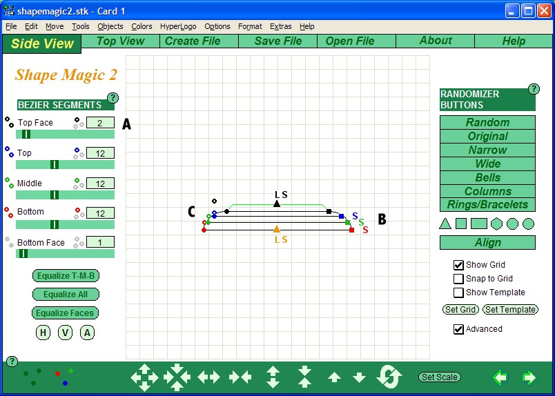
in Bryce. Knife Blade - Side ViewStep 1. To start, click on the square icon shown at A. This will give you a basic square to work from. Step 2. Now click on each of the square dots on the right of the shape. Hold down the mouse button as you drag the square dot into a new position. A - drag black square to top grid line and center on the grid (tip:
drop the square to the left of the center line and it will automatically
be centered)
Step 3. Before we finalize the shape of the blade, we need to set the number of bezier dots and segments. The top section of the blade is to have a shape that first curves one way and then back - so we want two bezier dots. Click on the icon at A until two colored dots appear. The middle section of the blade is short and only curves one way, so we only need one dot as shown at B. We could get by with only one dot for the bottom section, but for a more gentle curve we'll use two dots as shown at C. Usually I use about 12 bezier segments per section. But since we will be curving the blade, more segments help give the blade a smooth curve. I used 29 as shown at E. Either use the slide bar to set the value or click on the box and type in the number. For the middle section, since it is short, we can get by with only 7 segments as shown at F. The bottom segment uses 12 as shown at G. It doesn't hurt to use too many bezier segments, but they will make the model larger in memory.
Step 4. The final step is to drag the hollow dots into position. A - the lower blue hollow dot is placed above and to the left of the solid blue dot. That causes the line to curve out. B - the upper blue hollow dot is placed about 5 grid lines below the top and just to the left of center. This causes the line to curve back in and taper to the tip. C - the green hollow dot is placed about half-way between the blue and green solid dots. D - the upper red hollow dot is roughly aligned with dots A and C. This causes the line to have a smooth curve. E - the lower red dot is placed above and to the right of the solid red dot. We are finished with the side view.
|
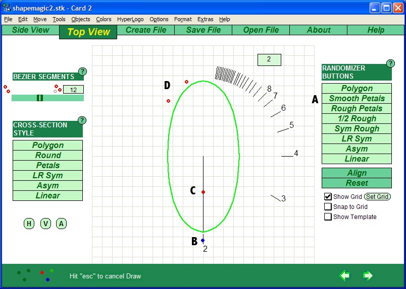
Knife Blade - Top ViewThe top view is looking down the length of the knife blade. First, we select a petal cross section by clicking the button Smooth Petals at A. Second, we drag the solid blue dot to the lowest position as shown at B. This makes the cross section have symmetrical right and left hand sections. Third, we drag the solid red dot up the center line to one grid line below center, as shown at C. This causes the cross section to pinch in at the middle. Fourth, we drag the lower red hollow dot to a position two grid lines above and to the left of the center point. This causes the slight bulging as shown at D. Finally, we place the upper red hollow dot about 2 grid lines above the center point. This causes the lines to taper to a point, creating the sharp knife edge. We are done with the top view.
|
Knife Blade - Create the CurveWe could leave the knife blade straight, but it looks more wicked with a curve. We want the knife to start with a straight section by the hilt. So on the create file page, we create a bend starting at 25% of the distance from the bottom of the model. The value is set as shown at A by clicking on a number in the green box. A pop up box will appear and lets you type in a new value. We stop the curve at 100%, so it curves all the way to the very tip. We want the knife blade to curve with the edge forming an arc. So we need to curve the model into the screen. So we type a value in the Angle I/O (for in/out) box. We want the curve to go beyond just a right angle, so we make it slightly larger (130 degrees). Because the model is curving into the screen, you won't be able to see what the curve looks like in the 3D preview unless you rotate the viewing angle. Click on the button at B and type in 90. Click on the button at C to get a preview. When satisfied with the curve, click on the button at D to create the model. Go to the Save File page and save it. Your model of the knife blade is ready to be imported into your 3D program.
|
Here's an image of the blade imported into Bryce. The model on the left is smoothed. The model on the right is not smoothed. You can see some of the rectangles that make up the mesh if you look closely.
Knife Blade VariationsHere's an example of some variants on the blade. The second model from the left is the curved blade with the bend turned off which leaves it straight. The 3rd model from the left is a straight blade with the lower blue hollow dot moved to the left and up to make a broader blade. The 4th model from the left is the original curved blade straightened and twisted 180 degrees. The last model on the right is the same twisted blade with both blue hollow dots moved to the left to make a broader blade with less taper to the tip. As you can see, the same basic model can make a lot of variants with just a few changes to the settings.
|
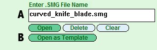
Knife Handle - Side ViewStep 1. Since we want the knife handle to match up with the knife blade, we'll use the template feature. I saved the knife blade model using the name curved_knife_blade. When the .obj file was saved, a .smg file was also saved with the same name. This file contains the design information. We'll open that file from the Open File page by typing the file name in at A and then clicking the button "Open as Template" at B.
Step 2. Returning to the Side View by clicking on the tab at the top of the screen, we check the box on the lower right marked "Show Template" as shown at A. The knife blade will show up as a yellow outline. We then click on the button labeled "Set Template" at B and type in the value 130. This raises the template on the page so we have some space to design the knife handle (C).
Step 3. Next we rough out the handle by dragging and dropping the colored squares. We put the black square right over the bottom right edge of the knife blade as shown at A. We then drag the blue square one grid line down and two grid lines to the left of the black square as shown at B. We drag the green dot to a position one grid line to the right of the center and two grid lines from the bottom as shown at C. And finally we drag the red square to a spot about one grid line from the bottom and 1 1/2 grid lines from the center as shown at D. Note that the hollow dots move along with the square dots.
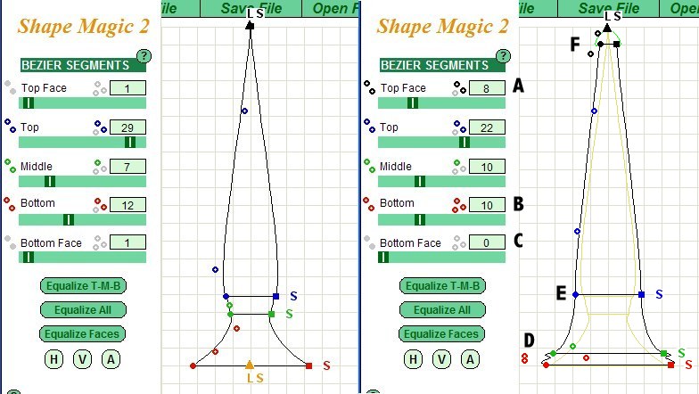
Step 4. Before finishing up the handle profile, we need to set the number of bezier dots and bezier segments as shown at A - E. We use one bezier dot at A because we are going to curve the upper face instead of leaving it flat. We also need to have about 12 bezier segments for a smooth curve. We use 3 dots and 14 segments as shown at B since this part of the model will have a complex curve. We use 2 bezier dots at C and D since these are simpler curves. There's fewer bezier segments at D since that part of the model is shorter. The bottom face is flat so we only need one segment and no dots as shown at E. Set the colored hollow dots as shown from F to I. There's a trick for setting the blue hollow dots which I'll cover in a minute. You also need to move the black triangle up slightly (see J) so the upper face has a smooth curve.
Step 5. To set the blue hollow dots, first click on the blue letter "S" as shown at A. This places the blue hollow dots in a straight line with the top, middle and bottom dots in the right order (T, M, B as shown in the figure at the left in the image). Drag the top and middle dots (T and M) to the position shown in the figure at the middle of the image above. The top dot (T) is placed about 1 grid line to the left and down from the bottom left edge of the knife blade. The middle dot (M) is placed about 1 grid line to the right and down from the top dot. One could stop there if you liked, but I wanted a thinner and more indented hilt, so I moved the bottom blue dot UP out of order, which forces the line to have a deeper curve as shown in the figure at the right of the image. The T and B dots are positioned so that the lower curve of the knife blade is continued along the hilt. Instead of a T, M, B order we have a B, T, M order.
Knife Handle - Top ViewThe top view is pretty simple. Just like the knife blade, it uses a Smooth Petal cross-section (click on the button shown at A). Drag the blue dot to the bottom so there are 2 sections (shown at B). Drag the red dot about half way up the vertical line (shown at C). Position the hollow red dots at the upper left of the outline as show at D. This makes a flattened oval cross-section for the handle. One could have used a circular cross section (by clicking on the button to the left marked Round) and resizing it in one direction within your 3D program, but I find making an oval within Shape Magic easier.
Here's an image of the handle imported into Bryce. The white model on the left is unsmoothed. The textured models were smoothed and had a brass texture added to the whole model. Then the middle section of each model was selected and a red leather texture added.
Just as we made different blades, here's a different handle made by moving a few of the hollow dots on the Side View. In no time, we could have a complete knife kit, with multiple blades and handles that could be mixed and matched.
|
Knife Sheath - Top ViewThe final object to be made is the sheath. We open the curved knife blade as a template from the Open File page so we can design the sheath around it. Then from the Side View, we make the changes as shown on the right of the image below. As shown at F, we are going to curve out the top face to make a ball at the end. So at A, we set two bezier dots and 8 segments. As shown at D, the bottom segment is going to be quite short but have a double curve to create a rim for the sheath. So at B, we set three bezier dots. At C, we want the sheath to be open, so we set the bezier segments to 0, which means there will be no bottom face. Next go to the green square and drag it down and to the right so it is near the red square. Then drag the red hollow dots into position as shown at D. Move the blue square dot to the right just a bit. Move the blue hollow dots to the left a small amount so the black line is outside the yellow outline of the blade. Move the green hollow dot down so the outline of the sheath is smooth from D to F. Position the black hollow dots as shown at F. The side view is now complete.
Knife Sheath - Top ViewGo to the top view. Everything is similar to the blade cross section except the red hollow dots are positioned as shown at A. The red solid dot is moved down as shown at C. The dots are adjusted so the area shown at B is smooth and somewhat flat.
Knife Sheath - Match the CurveThe settings at A are the exact same as for the knife blade, so the sheath fits perfectly
Knife Sheath Jewel - Side ViewTo add a touch of elegance to the sheath, we'll add a small jewel. This image shows the settings for the side view. Each section has 1 bezier dot, The top face has only 2 bezier segments, so we can have a flat top with a tapered edge as in a cut stone. The other sections have 12 segments so they give a smooth curve. Set the squares as shown at B and the hollow dots as shown at C. [Hint: I reuse this side view frequently with different top views to make pendants and various jewels. I just load in a previous copy of the .smg file to reestablish the design.]
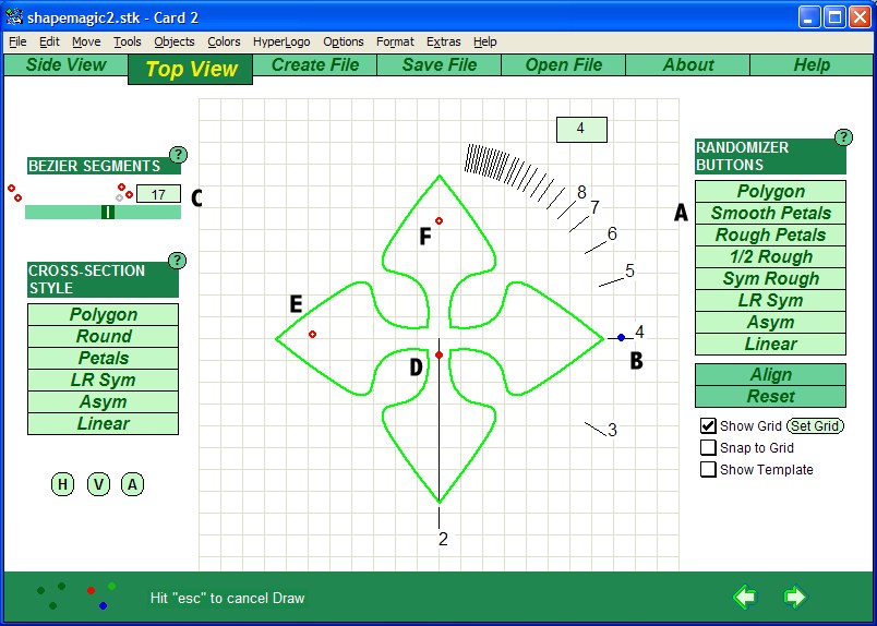
Knife Sheath Jewel - Top ViewThis is a complex top view. Click on button at A to set a smooth petal cross section. Set the blue dot at 4 as we want 4 petals to make a cross. Set the bezier segments at 17 as shown at B because we are going to have a deep indentation and still want a smooth curve. Set the red solid dot as shown at C and set the red hollow dots as shown at D and E. I won't shown the create file page, but all the settings are zero as we don't need to add any special effects.
Here the sheath and jewels were imported into Bryce and resized and fitted together. You can use whatever materials you want. A Shape Magic object has up to 5 sections that can have a different texture added to each. Here the sheath top and middle section have a leather texture added.
The completed model is shown in the image at the top of the page. |